Architectural freedom
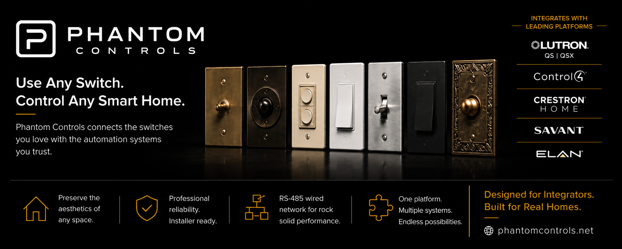
Keep real toggles, antique mechanisms, designer plates and existing wall switches—even in sensitive renovations and historic homes.
Professional smart-home infrastructure
Connect architectural, traditional, designer and vintage latching wall switches to modern automation—while keeping the control platform centralized at the rack.
The difference
Phantom creates a shared low-voltage switching layer, giving designers freedom at the wall and integrators centralized control where it is easier to configure and service.
Keep real toggles, antique mechanisms, designer plates and existing wall switches—even in sensitive renovations and historic homes.
A shared four-conductor field bus carries deterministic switch events without home-running every contact closure.
The simple wall-side layer stays consistent while receiver-side software bridges into the selected automation ecosystem.
How it works
A dry-contact switch at the wall becomes an addressed digital event, moves over RS-485 and arrives at the rack for local IP integration.
Use the latching dry-contact switch that fits the room.
Phantom-TX reads its state and applies a field-set ID.
TX nodes share the common 24V + RS-485 trunk.
Phantom-RX bridges field events to the control ecosystem.
Technical overview
Purpose-built hardware turns the mechanical state of a conventional latching switch into an addressed event and bridges it to a local IP smart-home system.
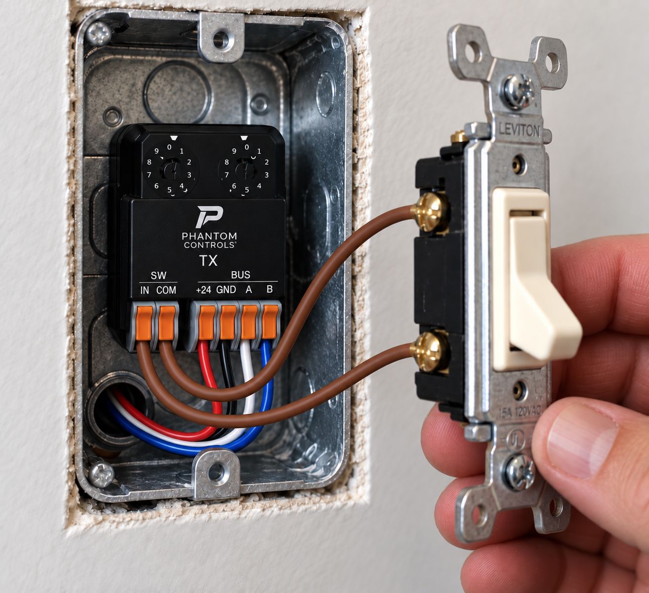
Phantom-TX
The transmitter reads a dry contact, applies a locally selected address and reports state changes over the shared bus.
Designed for latching switch inputs, not momentary-only keypad architecture.
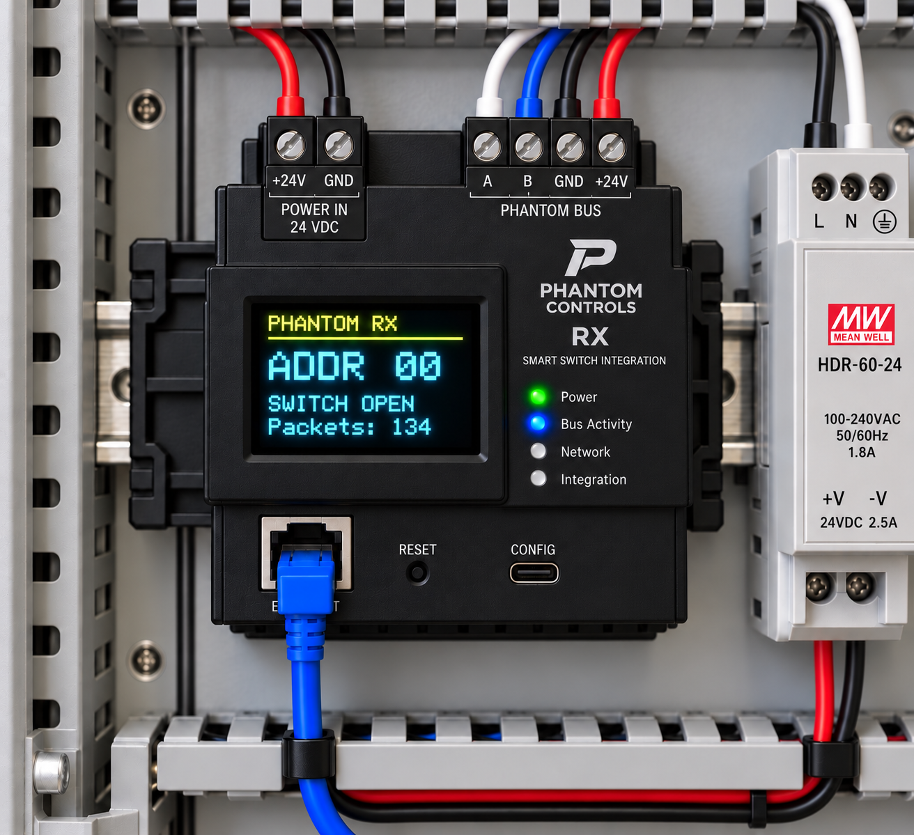
Phantom-RX
The receiver is the bridge between the deterministic field bus and the software-driven automation network.
Engineering details describe the current beta architecture and may change before production certification. Final cable limits, certification requirements and installation rules will be established through validation testing.
Integration targets
Receiver-side adapters are being developed so the physical switch infrastructure can remain stable while software integrations evolve.
Current stage
Hardware refinement, firmware hardening, integration validation and real-world beta preparation are underway.